Gameboy Dmg Powers On No Display

  1. Gameboy Dmg Powers On No Display Screen

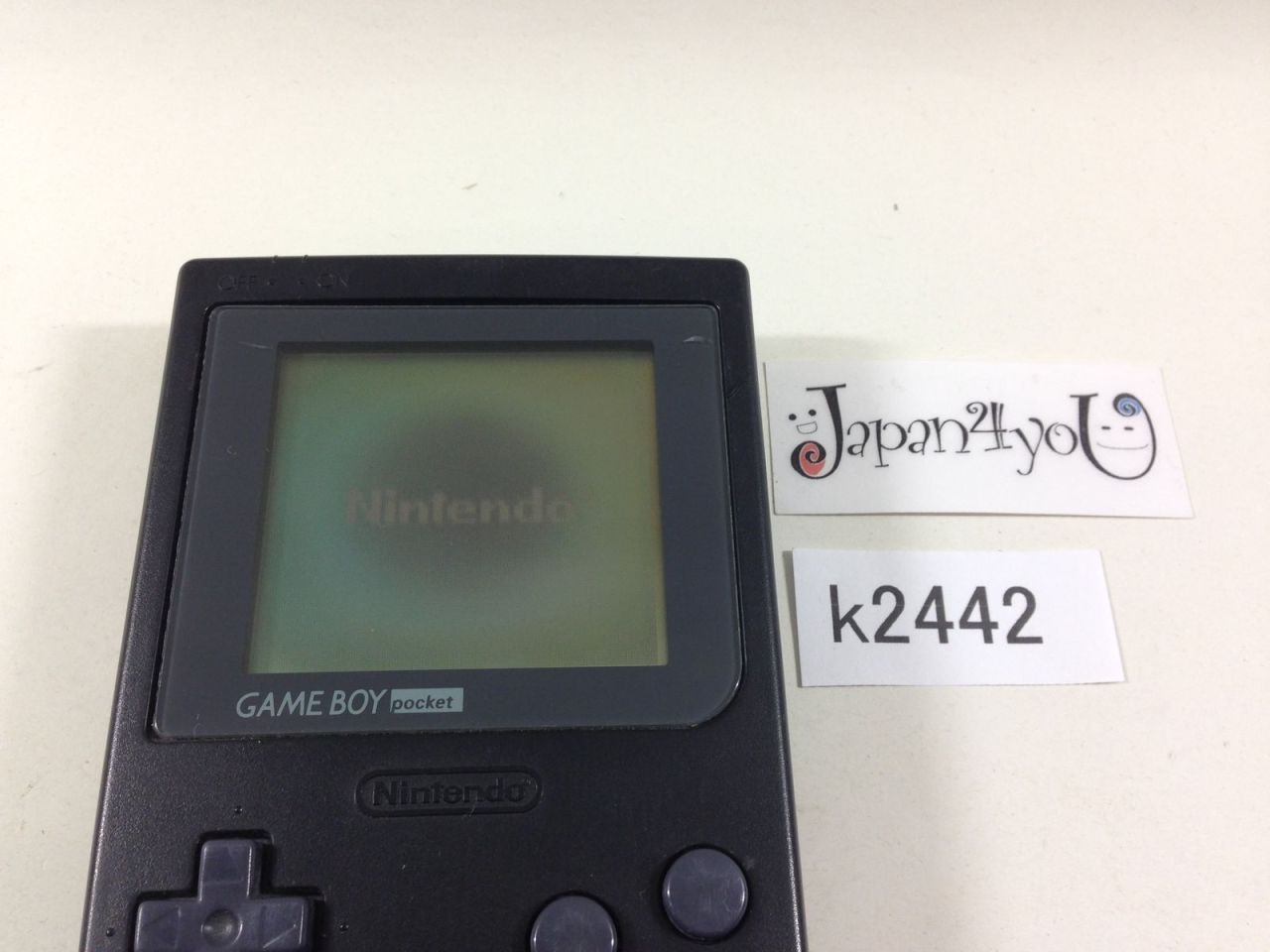
Hi, I have just bought a 1989 Gameboy DMG-01 in Hong Kong for dirt cheap. When i put batteries inside, there is one sound, red battery light is on and there is something on the screen. It looks like some black stripe going down on the screen I guess it's a logo. Then it shows something looking like chinese characters. The game I got is super 28 in 1. And than it stays like that, no sound, no reaction to pressing buttons, nothing. I would be really happy if I could fix it, looking forward to your tips, thank you.

Gameboy Dmg Powers On No Display
  • Turns on but then nothing. Hi, I have just bought a 1989 Gameboy DMG-01 in Hong Kong for dirt cheap. When i put batteries inside, there is one sound, red battery light is on and there is something on the screen. It looks like some black stripe going down on the screen I guess it's a logo. Then it shows something looking like chinese characters.
  • I put in a backlight and bivert kit a few days ago and the GAMEBOY DMG worked flawlessly for over 10 hours of gameplay. All the sudden the screen started randomly cutting out after about 5 mins of gameplay. Now the screen and sound will completely shut off after a few seconds. The screen has no horizontal or vertical lines.

Aug 23, 2016 GameBoy original DMG-01 Repair and Teardown for the common power fix. Battery contacts full of corrosion. Please comment if you have any questions. Share and Like. And of course Subscribe to.

Is this a good question?

Clean my drive 2 dmg. Comments:

Gameboy Dmg Powers On No Display Screen

Case


GameBoy Memory Map

The GameBoy contains an 8-bit processor, meaning it can access 8-bits of data at one time. To access this data, it has a 16-bit address bus, which can address 65,536 positions of memory. This address space is split into the following areas.
GameBoy Memory Areas
$FFFFInterrupt Enable Flag
$FF80-$FFFEZero Page - 127 bytes
$FF00-$FF7FHardware I/O Registers
$FEA0-$FEFFUnusable Memory
$FE00-$FE9FOAM - Object Attribute Memory
$E000-$FDFFEcho RAM - Reserved, Do Not Use
$D000-$DFFFInternal RAM - Bank 1-7 (switchable - CGB only)
$C000-$CFFFInternal RAM - Bank 0 (fixed)
$A000-$BFFFCartridge RAM (If Available)
$9C00-$9FFFBG Map Data 2
$9800-$9BFFBG Map Data 1
$8000-$97FFCharacter RAM
$4000-$7FFFCartridge ROM - Switchable Banks 1-xx
$0150-$3FFFCartridge ROM - Bank 0 (fixed)
$0100-$014FCartridge Header Area
$0000-$00FFRestart and Interrupt Vectors


$0000-$00FF - Restart and Interrupt Vector Table

The first 255 byte area in the Gameboy address space is reserved for Interrupt Vectors and Restart Vectors. Interrupts are a break in program code generated by a piece of the hardware when a certain condition is met. These conditions can be set by the programmer. There are several different types of interrupts, and when an interrupt is generated, the program stops where it is, and jumps to one of the specified locations in the Vector Table. The types of interrups are:
  • V-Blank - This interrupt can be generated when the LCD has drawn the last line on the screen and gone into the vertical blanking period. When this Interrupt is triggered, the CPU stores the current point of execution on the Stack, and jumps to $0040, which will usually contain another jump to the location of the code you want executed during the v-blank period.
  • LCDC - This interrupt can be generated by the LCD controller chip on various conditions, the most commonly used being the LYC condition, which is an interrupt generated when the LCD begins to draw a certain scanline. The scanline it generates an interrupt on is selectable. When triggered, this interrupt forces the CPU to jump to address $0048. For more information, see the section on I/O registers.
  • Timer - The system timer can be set to count at specified frequencies, and will increment a count register. When this register overflows, an interrupt is generated and the CPU jumps to $0050. More information in the I/O register section.
  • Serial - Generated by the serial link controller. The CPU jumps to $0058 when this interrupt is triggered. More info in the I/O register section.
  • Joypad - Generated when a key is pressed. Due to button 'bounce', this interrupt may occur several times when a button is pressed. More info in the I/O register section.

$0100-$014F - Cartridge Header Area

This area in the GameBoy address space contains information about the cartridge that is inserted, including; type of cartridge, size of rom, size of ram, a Nintendo logo, and other information. Also, at $0100, there is a NOP instruction, followed by a JUMP to the start of the program, usually $0150. The GameBoy's CPU begins execution at $0100, that is why this is included. If the Nintendo logo bytes are not correct, the GameBoy will not execute the game. Upon power up, the system ROM in a GameBoy will verify that the logo is correct. Nintendo has tried to use the logo to keep only authorized developers from publishing games, since the logo is a registered trademark of Nintendo. But, a legal precedent was set in the United States in a case of Sega vs. Accolade (c.1993). Sega's Genesis console also has a signature that is a copyright of Sega, and Accolade used this logo so that their games, which were not approved by Sega, would be able to play on the Genesis console. The judge ruled in favor of Accolade, stating that using a logo to that degree was an anti-competetive practice, and therefore, Accolade was allowed to continue selling their games. At least, that's what I heard. =P
Cart Header
$0100-$0103NOP / JP $0150
$0104-$0133Nintendo Logo
$0134-$013EGame Title (Uppercase ASCII)
$013F-$01424-byte Game Designation
$0143Color Compatibility byte
$0144-$0145New Licensee Code
$0146SGB Compatibility byte
$0147Cart Type
$0148Cart ROM size
$0149Cart RAM size
$014ADestination code
$014BOld Licensee code
$014CMask ROM version
$014DComplement checksum
$014E-$014FChecksum

$0150-$3FFF - ROM Bank 0

Realistically, ROM Bank 0 includes all the data from $0000 to $014Fm but they were special areas, so I made them separate. ROM Bank 0 is the home bank. It's the fist 16K bank of any ROM image, and is a fixed bank, which means you can't switch it out with other banks, like you can with the next section (which is discussed in the next section). When the GameBoy powers up, program execution starts at $0100, which almost always has a jump to $0150 (jp $0150), the first byte of free space. So really, $0150 will be the start of your programs. Since this bank is fixed and CANNOT be changed out, it usually contains the majority of the game's engine, or core routines. So I guess you could say that instead of programming a 64K address space, you're actually restricted to 16K for most things.

$4000-$7FFF - ROM Bank n

This is where alot of your game data will exist.. in this 16K space. This area is switchable or banked. You can switch in 16K chunks of the entire ROM in this area, through the use of the Memory Bank Controller (MBC) on the cartridge. How the MBC works is you basically 'write' to an area in ROM, and since ROM is by nature READ ONLY MEMORY, writing a value to ROM is futile, except in the case of the MBC. It intercepts the attempted write to ROM and interprets it into a bank switch. the value you try to write to ROM is generally the bank number you want to change to. For example, when using MBC1, one would do this to change to bank 5:
  • LD A,5
  • LD HL,$2000
  • LD (HL),A
The first line loads the value 5 into register A. The second line loads register pair HL with $2000, our destination address. The third line loads the value in register A into the address indexed by register pair HL. Easy, right?

$8000-$97FF - Character RAM

This area is RAM inside the GB unit, and is used exclusively for video purposes. This area is also known as Tile RAM, since it holds tiles. Each tile is 8x8 pixels of 2-bit color, which makes each tile 16 bytes long. This area is also divided up into two modes of tiles, signed and unsigned. In unsigned mode, tiles are numbered from 0-255 at $8000-$9000. In signed mode, tiles are numbered in two's complement from -127 to 128 at $87FF-$97FF. I think.. lol. Generally most ppl use 0-255 tiles, since it's nice and easy.

$9800-$9BFF - BG Map Data 1

This 1024-byte long area is what the video processor uses to build the display. Each byte in this space represnts an 8x8 pixel space on the display. This area is 32x32 tiles large.. EG: 1024 bytes. The display processor takes each byte and then goes into the Character RAM area and gets the corresponding tile from that area and draws it to the screen. So, if the first byte in the Map area contained $40, the display processor would get tile $40 from the Character RAM and put it in the top-left corner of the virtual screen. I say virtual screen because the actual LCD is only 160x144 pixels in size and is basically a viewport that can be scrolled around the 32x32 tile (256x256 pixel) background area in video memory.

$9C00-$9FFF - BG Map Data 2

This area is just a second background map area like the previous one. To specify which map the video processor uses to build the background image, change the apropriate bit in the LCDC I/O register, explained later.

$A000-$BFFF - External (cartridge) RAM

If present on the cartridge, this area is mapped to the RAM on the cartridge.

$C000-$DFFF - Internal Work RAM

This RAM in inside the GameBoy. Generally used for most common variables and such in games.

$E000-$FDFF - Reserved Area/Echo RAM

This area echoes internal ram, but is specified by Nintendo as reserved and shouldn't be used at all. To keep with standards and to keep compatibility, don't use this area.

$FE00-$FE9F - Object Attribute Memory (OAM)

OAM is sprite RAM. This area is 40 sprites X 4 bytes long. When you with to display an object (sprite) you write 4 corresponding bytes to OAM. These 4 bytes are:
  • Byte 1: X Location
  • Byte 2: Y Location
  • Tile Number (0-255)
  • Attributes
The tile number is taken from the Character RAM, just a BG tiles are. The X and Y locations are slightly offset (8 pixels and 16 pixels), so you can have sprites partially off of the left and top of the LCD. So if you set the location to 0,0 then the sprite would be off of the screen. To set a sprite to the top-left corner, you'd set it's location to 8,16. Piece of cake. ;-)

$FEA0-$FEFF - Unused

And it'd be smart to leave it that way. =)

$FF00-$FF7F - Hardware I/O Registers

This area contains all the control registers for all the hardware on the GameBoy and is basically a memory-mapped I/O area. Details on this area are in another section.

$FF80-$FFFE - High RAM Area

Originally intended to be used as 127 bytes of stack space, this area is better suited for use as a Zero-Page, or a quick RAM access area, since there is an instruction that accesses the area $FF00-$FFFF quicker than a regular LD instruction. Most coders nowadays just set the stack to the TOP of internal RAM, since it works the same and frees the high RAM for quick variables and such.

$FFFF - Interrupt Enable Register

This is another I/O register, which controls the interrupts.


This webpage was designed to be viewed in any HTML 4.0/CSS1 compliant browser, but since Netscape sucks (opinions are like ass holes, everybody has got one), everything looks like sh*t in Netscape, so go get IE 5.5 or Opera 4.0, which both are great browsers (and consequently, display my webpage correctly).
DISCLAIMER: You will NOT find commercial ROMS on this website, nor will I answer e-mail in regards to where you can find ROM's on the Internet. Downloading a ROM image of a game you do not own is illegal. I will not answer e-mail regarding PokémonTM. This website, to the best of my knowledge does not contain any illegally obtained information, nor any illegal content. Not everything on this webpage was created by me. Some of the content, images, etc, have come from many places, and I thank the friends who have helped me with everything (that means you Sacher!).Should you not like my views, opinions, ideas, etc, etc, then pardon me and PISS OFF.


Comments are closed.